I think 's solution with n/s/e/w in parts editor will also add the terminalId field however I usually have difficulty making that work so am more inclined to edit the file. I’ll add this to my list of things I should fix in the script, since it knows the connector number and could (and should!) display it in the error message to be more helpful. You would need to edit the fzp file and look at line 4910 to discover that this refers to pin 323 (big part!). TerminalId missing in schematicView (likely an error)įor all the missing pins.


The part check script provides this somewhat (because it lacks a connectorId) warning message: So your easiest solution is likely to use a text editor to add the missing temrinalId fields to the connectors that don’t have one in the fzp file. For example connector9 (the first one I happened to try in Fritzing ) looks correct in the svg but the fzp is missing the terminalId tag: The terminals look to be there and correct in the schematic svg, but aren’t in the fzp file. It looks like your problem is the fzp file. Does was that you meant when you do the “rescale” step previously mentioned on my other topic? So far, it has worked as my piece has the same size as the arduino mega breadboard. Fritzing does try to correct for this problem, but your safest bet may be to open your Illustrator-based SVG in a text editor and hand-modify the width and height attributes by dividing each by 72 and putting “in” (meaning inches) as the units.Īfter looking at it, I set my file preferences on inch units and changed the dpi from 72 to 90 as stated above. So when you save images from Illustrator, if you want them to show up at the size you expect in Fritzing, save the image in units other than px (and note that if you leave out units entirely, it means “px”).

The most annoying quirk with Illustrator is that Illustrator defines a pixel (“px”) as 72dpi, whereas in the SVG standard, a “px” is 90dpi. I saw something related to that on the documentation so better stick with Illustrator and try if I can fix it on my own.Īlso, speaking of the github docs, while reading the part file format section, I found this: Yeah, it would be useless due to the compatibility between both software. I can fix it up in Inkscape for you easily enough, but if as last time that doesn’t translate well to Illustrator it may not help much.
#SHIELD ARDUINO MEGA PINOUT HOW TO#
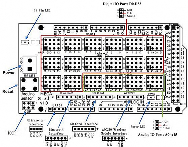
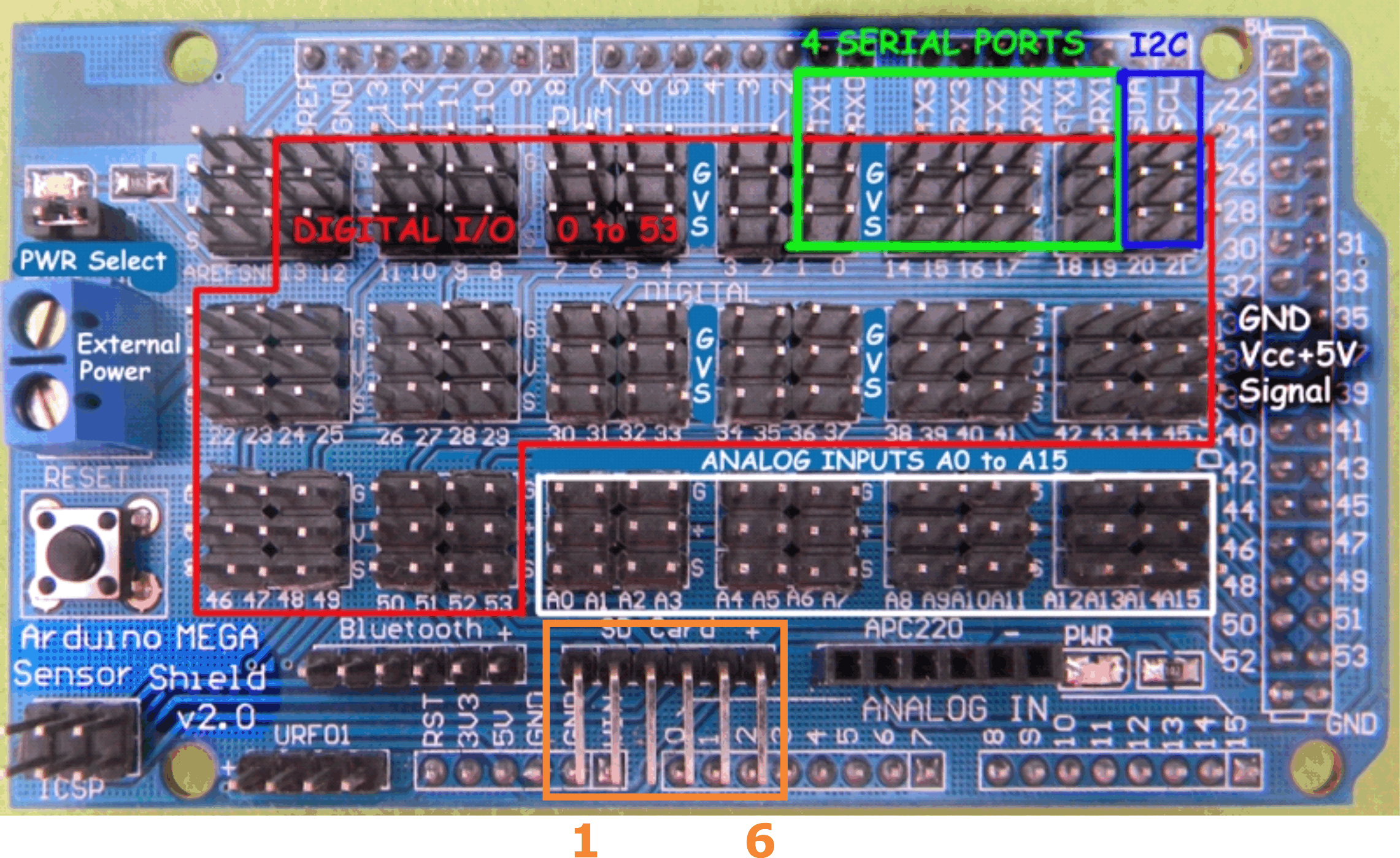
I don’t know how to do the same in Illustrator but I expect someone here probably does. Again this part is exported as a bin (.fzbz file) rather than a part (fzpz file) which is preferable. If as Old_Grey indicated the problem is in breadboard, there you have some transforms which ungrouping everything should remove although the spacing in Inkscape looks correct. I’d start by exporting a copy of the original board you used and make sure there its pcb and/or bb (unmodified) is correct, its possible the part you cloned from is incorrect. 1 in as it should be, so I assume the pins are misaligned in x or y against a real board? There don’t appear to be any transforms on the pcb svg (which is the usual problem with scaling problems) so there likely isn’t a quick fix per se, you would need to ungroup the copper layers (because otherwise Inkscape will use transforms) and move select a group of pads and move them in x and y to correct the alignment. The pcb svg looks like the spacing is close to. The board size is slighty misplaced when placing over the arduino mega board. I used the guidelines for the 0.1 inch separation between connectors and used the same PCB from the arduino mega 2560 rev3. The board size is slighty misplaced when placing over the arduino mega board.Following the first problem, I have to add the same ammount of GND (a.e) on my schematic file? There isn’t a workaround for it?.Does that mean I have to define like +100 pins in order to make all of them work? I tried sharing the GND pins but wasn’t successful. The breadboard has a lot of header pins (G = GND, V = Vcc, S = Signal) along with the grey squared ones.I tested it as you told me on the other topic and it has not loading error fzpz one:Īrduino_MEGA_sensor_shield_v2.fzbz (143.0 KB)

fzp file after trying to set up all the pins (took a bit to accomplish) inside the. Greetings am struggling about multiple things after following your tips, reading the documentation and the “new parts” tutorial.įirst, here are the multiple svg files along with the.


 0 kommentar(er)
